Discover High-Quality Selvedge Denim Fabric from WingFly Textiles
The global denim market is set to expand, driven by a growing demand for premium denim. At the forefront of this trend stands WingFly Textiles, a top manufacturer. They deliver outstanding selvedge denim fabric to international clients.
WingFly Textiles, based in China, is celebrated for its dedication to quality and innovation. Recognized as a dependable Gold selvedge denim fabric manufacturerssupplier, they present a broad selection of denim fabrics. This includes raw denim and customized materials, meeting the diverse needs of their international customers.
Noteworthy Points
- WingFly Textiles stands as a top producer of premium selvedge denim fabric.
- They supply wholesale premium denim fabric and bespoke raw denim materials.
- Headquartered in China, they cater to customers worldwide.
- They’re known as a dependable wholesale selvedge denim supplier.
- Their catalog features raw denim alongside tailored denim materials.
Welcome to WingFly Textiles: Your Go-To Selvedge Denim Source
Boasting deep roots in denim craftsmanship, WingFly Textiles is the go-to for premium selvedge denim fabric. We are dedicated to quality and innovation, making us a leading supplier of high-quality denim fabrics to the textile industry.
Our history in denim production is built on deep knowledge and unwavering standards. We’ve honed our techniques and adopted cutting-edge machinery through the years. This guarantees our offerings uphold the utmost quality.
Our Rich History in High-End Denim Production
We take pride in our long-standing heritage of crafting top-quality denim with meticulous attention. Through years of expertise, we create denim that is tough yet full of character.
Our facility includes 120+ vintage shuttle looms, plus two selvedge jacquard-specific looms for unique patterns. This capability allows us to offer a diverse range of denim products, catering to various client needs.
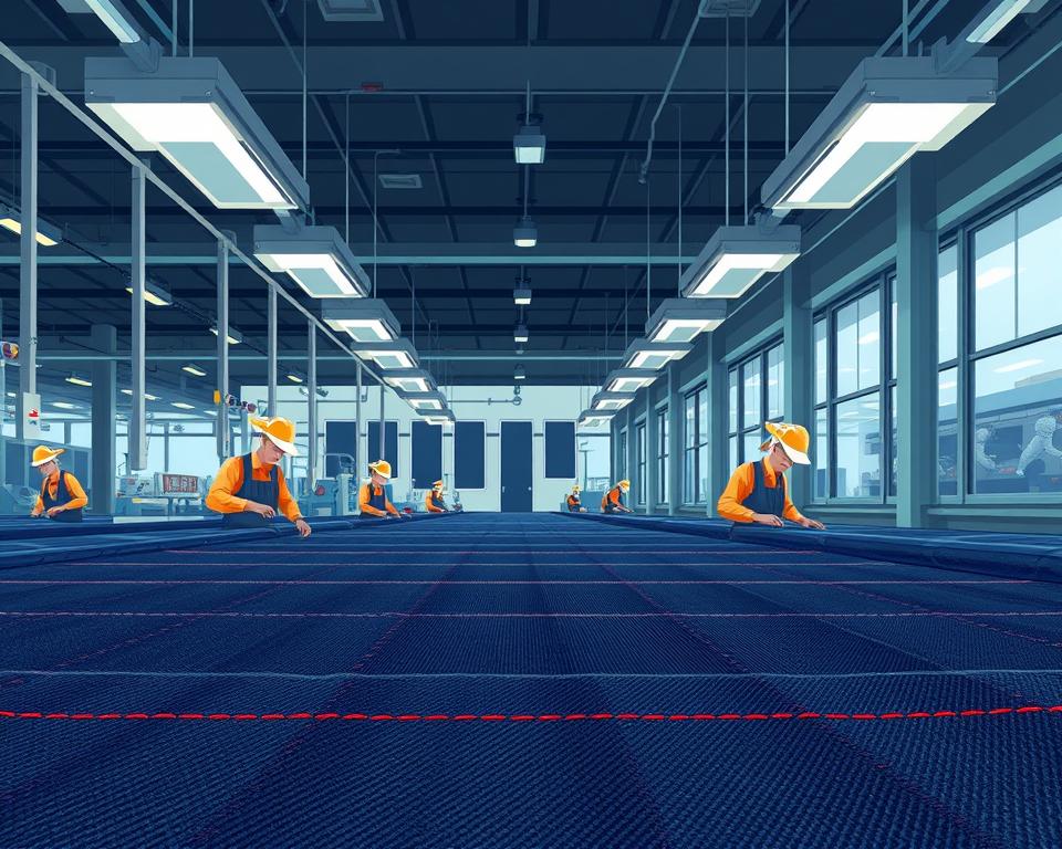
Advanced Production Setups
Our state-of-the-art production facilities are the backbone of our operations, enabling us to maintain the highest quality standards. Blending cutting-edge equipment with time-tested methods, we deliver premium selvedge denim.
Our capabilities span gold selvedge to striped denim, thanks to our expert looms. Through advanced weaving processes on specialized looms, we achieve this variety.
| Production Capability |
Description |
Output |
| Shuttle Looms |
Old-fashioned shuttle looms for traditional denim weaving |
High-quality selvedge denim fabric |
| Jacquard Looms |
Specialized looms for intricately designed patterns |
Selvedge jacquard denim fabric with unique designs |
| Weaving Techniques |
Combination of traditional and modern weaving methods |
Diverse range of denim fabrics, including striped and gold selvedge denim |
Global Distribution Network
Through a comprehensive distribution system, we bring our slub denim to international markets. Our ability to deliver high-quality products efficiently has made us a trusted partner in the textile industry.
From gold selvedge to striped denim makers, our facilities accommodate all needs. With worldwide reach and unwavering quality focus, we’re the go-to for dependable denim sourcing.
We pledge to provide top-notch products and unmatched service to every client. Our focus on quality, combined with our extensive industry experience, positions us as a leader in the selvedge denim fabric market.
All You Need to Know About Selvedge Denim Fabric
Learn how selvedge denim is made, what sets it apart, and why it commands a premium. Fundamentally, selvedge denim comes from a vintage shuttle loom. It creates a slim, compact border on each side of the cloth. That edge not only offers a distinctive look but also enhances durability.
Selvedge denim’s roots trace back to denim’s traditional past. Shuttle-loom weaving yields a firmer, more compact fabric structure. This tight weave is key to the fabric’s robustness and its ability to resist fraying. Hence, selvedge denim is favored for premium denim goods.
What sets selvedge denim apart is its edge treatment. In contrast to cut selvages, selvedge denim features a neat, woven edge. This edge is less likely to fray, making it ideal for jeans and other items where the raw edge is exposed.
From classic indigo to textured slub denim or colorful rainbow selvedge denim, myriad options exist. With uneven yarn thickness, slub denim offers a distinctive tactile appeal. Rainbow selvedge denim sports a vibrant edge that enhances garment aesthetics.
As a leading selvedge denim supplier, WingFly Textiles provides a selection of premium selvedge denim fabrics. From timeless indigo to experimental slub or rainbow selvedge, we meet every specification.
Key Features of High-End Selvedge Denim
Several hallmark traits define top-tier selvedge denim’s excellence and aesthetic. As an expert wholesale selvedge denim supplier, we employ the finest cotton yarn. This produces denim fabrics that excel in the market.
Selvedge Edge Craftsmanship
Selvedge denim’s border-finishing methods are truly distinctive. In contrast to cut denim, selvedge denim employs traditional shuttle weaving. The outcome is a neat, self-finished edge resistant to unraveling. This feature not only boosts the fabric’s durability but also adds a vintage charm.
Shuttle Loom Techniques
Selvedge denim’s weaving is a meticulous, heritage-driven process. This uses shuttle looms to craft a tighter weave. That approach amplifies durability and tactile appeal, adored by denim aficionados.
Weight Categories of Selvedge Denim
We offer premium rainbow selvedge denim in multiple weight and density options. There are lightweight fabrics for spring and summer and heavier, raw denim for rugged wear. The range includes herringbone selvedge denim fabric, known for its reversible pattern and durability.
As a respected selvadge raw denim fabric wholesaler, WingFly Textiles offers a wide range of weights and weaves. So every client locates the perfect fabric for their creations.
Exploring Our Signature Black Selvedge Denim Collection
The signature black selvedge denim series exemplifies supreme craftsmanship at WingFly Textiles. As a leading wholesale selvedge denim supplier and raw denim wholesaler, we pride ourselves on delivering top-notch denim fabrics to a wide range of clients.
Crafted from top-grade cotton yarn, our black selvedge denim guarantees long life and comfort. It comes in various weights and densities, fitting perfectly into the fashion industry’s diverse needs. Whether you’re a selvedge denim fabric distributor or a fashion brand, our denim meets your exact specifications.
No other black selvedge denim range matches its adaptability. Great for crafting jeans, outerwear, and even fashion accessories. Our commitment to quality and service has made us a denim industry mainstay.
Our international supply chain delivers consistently and quickly everywhere. This line reflects our steadfast devotion to superb quality and innovative fabric design.
Understanding Nep Denim’s Unique Appeal
Nep denim fabric is celebrated for its unique, irregular texture. It sets nep denim apart in the textile landscape. As a bulk denim fabric supplier, WingFly Textiles values the distinct qualities nep denim brings to fashion.
By weaving in small yarn clusters called “neps,” nep denim gains texture. It crafts an eye-catching, grainy texture. Through yarn selection and weaving adjustments, nep textures emerge.
Handcrafted vs Automated Nep Denim
Its appeal springs from the interplay of heritage and technology. Traditional methods involve manual processes, resulting in unique, irregular textures. By contrast, automated looms create repeatable nep effects.
- Traditional techniques offer a one-of-a-kind texture and character.
- Modern methods provide consistency and scalability for large orders.
Applications in Contemporary Fashion
Nep denim is highly valued in contemporary fashion for its distinctive look and feel. As a premium denim fabric wholesaler, WingFly Textiles supplies nep denim to designers who appreciate its unique texture and character.
Nep denim finds use in several standout applications:
- Designing standout items showcasing nep character.
- Enriching collections with assorted nep motifs.
- Boosting garment visuals through textured interest.
For selvedge jeans fabric suppliers and other denim manufacturers, nep denim offers a way to differentiate their products. It enriches product lines with artisanal flair.
Gold Selvedge: Opulence & Strength
As a foremost wholesale supplier, WingFly Textiles unveils gold selvedge denim. This fabric combines luxury with unmatched durability. Made from high-quality cotton yarn, it ensures a premium product for our clients worldwide.
The gold selvedge denim fabric comes in various weights and densities. Perfect for a range of apparel applications. From breezy summer weights to robust winter weights, choose what you need.
Opulence with resilience define our gold selvedge denim. Superior yarn and modern weaving craft a plush yet hardy fabric.
| Weight Classification |
Density |
Recommended Use |
| Lightweight |
8 oz |
Summer clothing, dresses |
| Mid-weight |
10 oz |
Casual wear, jeans |
| Heavyweight |
12 oz |
Winter wear, heavy-duty jeans |
As an indigo denim fabric distributor and black selvedge denim fabric wholesale supplier, WingFly Textiles is dedicated to quality. The gold selvedge collection highlights our denim mastery.
Innovation in Striped Denim Fabric Manufacturing
As a front-runner in striped denim, WingFly Textiles innovates across raw and selvedge lines. Using advanced systems, we meet the needs of everyone from trend-setting brands to gold selvedge mills. Their aim is crafting impeccable striped denim textiles.
The innovation spans various techniques and technologies. Among these, vertical stripe weaving stands out.
Precision Vertical Stripe Weaving
Vertical stripe technologies have transformed striped denim fabric production. Using innovative looms, we deliver accurate, uniform vertical stripes. It enhances both the look and longevity of the denim.
Complex Horizontal Weave Designs
Our horizontal stripe design capabilities are unmatched. They weave elaborate designs adding distinctive style to denim. Their advanced facilities ensure these patterns are executed with precision, meeting the fashion industry’s high standards.
Custom Stripe Solutions
WingFly Textiles caters to diverse client needs with custom stripe solutions. By partnering closely, we develop exclusive stripe patterns for brands. For gold selvedge mills, our custom stripes provide a competitive edge.
See below for our striped denim production strengths:
| Feature |
Description |
Benefit |
| Vertical Stripe Technologies |
Advanced weaving techniques for precise vertical stripes |
Enhanced aesthetic appeal and durability |
| Horizontal Pattern Development |
Intricate patterns for unique denim fabrics |
Exclusive designs for fashion brands |
| Custom Stripe Solutions |
Tailored solutions for specific client needs |
Flexibility and exclusivity for clients |
A trailblazer in stripe denim production, WingFly Textiles sets the standard. They combine tech prowess with bespoke services. As a raw denim and selvedge denim fabric supplier, they aim to meet the fashion industry’s evolving demands with high-quality fabrics.
The Unique Appeal of Slub Denim
With its slub-induced texture, no two slub denim pieces are ever alike. As a top selvedge material supplier, we present superior slub denim. Ideal for varied fashion designs.
By twisting yarns strategically, slub denim gains its signature texture. It’s a go-to for design houses crafting statement items.
We know slub denim’s power to transform garments into art. Our slub denim maintains top-tier quality for contemporary applications.
Want to stand out or add depth to your lines? Choose our slub denim or rainbow selvedge denim for both flair and fortitude.
Rainbow Selvedge: Adding Color to Traditional Denim
WingFly Textiles brings a vibrant twist to traditional denim with its Rainbow Selvedge denim fabric. Crafted from high-quality cotton yarn, this fabric comes in a variety of colors and patterns. It’s perfect for the fashion industry’s diverse needs.
As a leading selvedge denim fabric wholesaler, WingFly Textiles offers customization to its clients. This includes other wholesalers seeking unique denim fabrics. Expert craftsmanship locks in both resilience and eye-catching color.
Color Integration Techniques
Rainbow Selvedge production uses cutting-edge color weaving. At WingFly Textiles, our team employs cutting-edge technology. This ensures colors are evenly distributed, resulting in a consistent, high-quality finish.
- Advanced dyeing processes to achieve vibrant colors
- Exact color placement for uniformity
- Top-tier cotton yarn for strength and softness
Bespoke Color & Pattern Services
We recognize each client’s unique vision. Custom Rainbow Selvedge solutions are available. Whether you’re a fashion designer or a wholesaler, we can tailor our denim to your specifications.
Our customization capabilities include a wide range of colors, patterns, and bespoke designs. As a reputable herringbone selvedge denim fabric supplier and selvadge raw denim fabric wholesaler, we aim to deliver products that exceed expectations.
The Elegance of Herringbone Selvedge
Being premier wholesalers, we feature herringbone selvedge denim. With superior cotton yarn, it combines resilience and comfort. It adheres to elite criteria for both durability and design.
The herringbone pattern is achieved through a unique weaving technique. It elevates aesthetics and signals luxury craftsmanship.
Our herringbone selvedge is available in diverse weights and feels. Suitable for every style segment. Designers and wholesalers alike favor our herringbone selvedge.
We, as a selvedge denim fabric distributor, supply our herringbone selvedge denim globally. Fast logistics and value pricing are our promise. Quality focus and service excellence underline our industry trust.
Raw Selvedge Mastery: Fiber-to-Fabric
At WingFly Textiles, we take pride in our raw denim excellence. As bulk and premium suppliers, we recognize superior raw denim’s worth. Crafted from select cotton yarn, they promise optimal outcomes.
Premium Cotton Sourcing
Top-quality raw denim hinges on superior fiber choice. We pick the finest cotton fibers, looking at length, strength, and color. Guaranteeing raw denim of the highest caliber.
- Fibers are tested for tensile resilience and uniformity.
- Color consistency is checked to ensure uniformity.
- Only the finest fibers make it into our looms.
Detailed Weaving Parameters
Post-fiber selection, we weave the cloth by heritage techniques. We maintain exact standards of fabric mass, compactness, and surface. As selvedge jean purveyors, we ensure flawless edge integrity.
| Weaving Specification |
Description |
Benefit |
| Weight |
Varied weights to suit different applications |
Flexibility for different garment types |
| Density |
Carefully controlled to achieve desired texture |
Enhanced durability and comfort |
| Texture |
Unique textures achieved through traditional weaving |
Aesthetic appeal and character |
Quality fiber meets exact weaving in our raw denim. This results in durable fabrics with a unique character. Brands and enthusiasts alike find our denim unparalleled.
Quality Control Standards at WingFly Textiles
WingFly Textiles is dedicated to delivering top-notch quality. As a leading denim fabric wholesale supplier, we know how critical it is to uphold the highest standards in our products.
From fiber inspection to finished rolls, our QC is comprehensive. We only use prime fibers and cutting-edge looms. This ensures our denim fabrics meet the required specifications. We prioritize consistent indigo coloration. We aim for a rich and consistent indigo color across our product lines.
For our black selvedge denim fabric wholesale customers, we follow strict quality control measures. Key QC steps include:
- Stringent raw fiber testing
- Cutting-edge textile processing
- Detailed inspections across all phases
Maintaining such rigor cements our role as a go-to wholesaler. Our dedication to quality is steadfast. We ensure our customers receive the best products for their needs.
Our mission: unmatched quality and service. These standards embody our pursuit of textile perfection. Geared to adapt as trends shift.
Green Initiatives in Textile Production
As a leading raw denim and selvedge denim fabric supplier, we focus on sustainable practices. We strive for greener manufacturing. Serving top-tier brands with responsible production.
Our modern plants and techniques showcase our green focus. We strive to reduce our environmental impact through various initiatives. Maintaining excellence while protecting the planet.
Water Conservation Methods
Saving water is central to our green strategy. We use state-of-the-art water recycling systems. Cutting usage dramatically. Key tactics include:
- Adopting closed-loop water recycling
- Employing low-water dye methods
- Ongoing maintenance to curb water loss
Sustainable Coloration Techniques
Conventional dye methods pose ecological risks. We now use green dye techniques to mitigate harm. Our approach includes:
- Employing non-toxic, low-impact dyes
- Digital print processes to minimize waste
- Piloting foam and ozone dye processes
Waste Reduction Initiatives
Reducing waste is a critical aspect of our sustainability strategy. We’ve implemented various initiatives to minimize waste. Highlights include:
- Precision cutting for less waste
- Recycling fabric scraps and reusing them in other products
- Aligning with green-certified suppliers
By integrating these sustainable practices, we reduce our environmental impact. We also enhance the quality and uniqueness of our selvedge denim fabric. As a responsible supplier, WingFly Textiles is dedicated to making a positive difference in the textile industry.
Bespoke Services for Bulk Buyers
At WingFly Textiles, our custom development services empower wholesale clients to realize their denim dreams. With deep industry insight and innovative spirit, we deliver custom solutions. This allows us to provide tailored solutions that cater to our clients’ unique needs.
Seeking premium selvedge, slub character, or rainbow flair? We pledge to craft standout fabrics. From signature selvedge to specialty textures, our lineup sets clients apart.
Clients tap into our advanced looms and deep denim know-how. Our joint mission: exceptional denim creation. Boost your brand with our bespoke denim offerings.
Place Your Order for Premium Selvedge Denim
Ordering our premium selvedge denim is easy and efficient. As a top supplier of herringbone selvedge denim fabric and selvadge raw denim fabric wholesaler, we guarantee top-notch products and service. Our mission: your utmost delight.
MOQs & Lead Times
We balance MOQs to best serve you. Requirements differ by denim style and order size. Our team is ready to go over these details with you.
Fabric Sampling
Before a big order, we suggest our clients try our sampling process. Assess our denim firsthand. We guarantee sample accuracy.
Contact sales to request samples. We’ll arrange prompt sample delivery so you can approve the fabric.
Conclusion: Partner with WingFly for Superior Selvedge Denim
WingFly Textiles stands out in the denim world, known for quality and innovation. We serve as a top wholesale selvedge denim supplier. Our range suits every raw denim and selvedge distributor worldwide.
Collaborating with WingFly Textiles opens doors to a wide range of premium selvedge denim fabrics. These are crafted with meticulous attention to detail. State-of-the-art plants and global logistics guarantee on-time, quality shipments.
At WingFly Textiles, we focus on sustainability and customer happiness. We create denim for the future of style. Our green initiatives shrink our footprint.
We welcome you to explore our selvedge lineup. See why WingFly sets the standard. Join us in our quest to provide outstanding quality and service to the fashion world.